
20260302 - U-Boot移植与调试指南
U-Boot(Universal Boot Loader)是嵌入式Linux系统的引导加载程序上电 → MiniLoader(TPL/SPL) → U-Boot → Linux Kernel → 根文件系统↑ ↑初始化DDR 初始化硬件、加载内核阶段名称运行位置主要功能1SRAM初始化DDR内存2DDR加载U-Boot3U-BootDDR初始化硬件、加载内核4DDR操作系统内核5RootFSDDR
U-Boot移植与调试指南
文档信息
- 项目: 5G/WiFi高清执法记录仪
- 平台: RV1126B (ARM Cortex-A53, 64位)
- U-Boot源码路径:
/home/alientek/atk_dlrv1126b_linux6.1_sdk/u-boot
目录
一、U-Boot的作用
1.1 什么是U-Boot
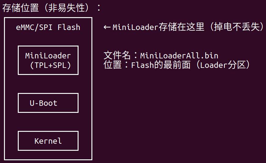
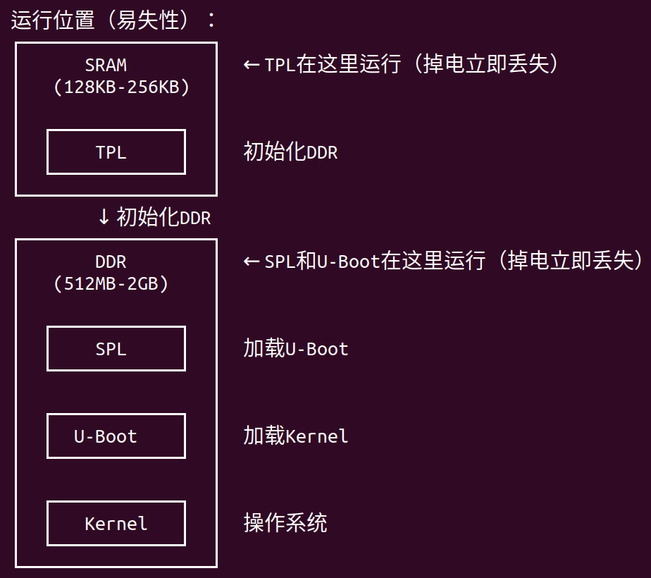
U-Boot(Universal Boot Loader)是嵌入式Linux系统的引导加载程序,它在系统启动流程中的位置:
上电 → MiniLoader(TPL/SPL) → U-Boot → Linux Kernel → 根文件系统
         ↑                      ↑
      初始化DDR            初始化硬件、加载内核
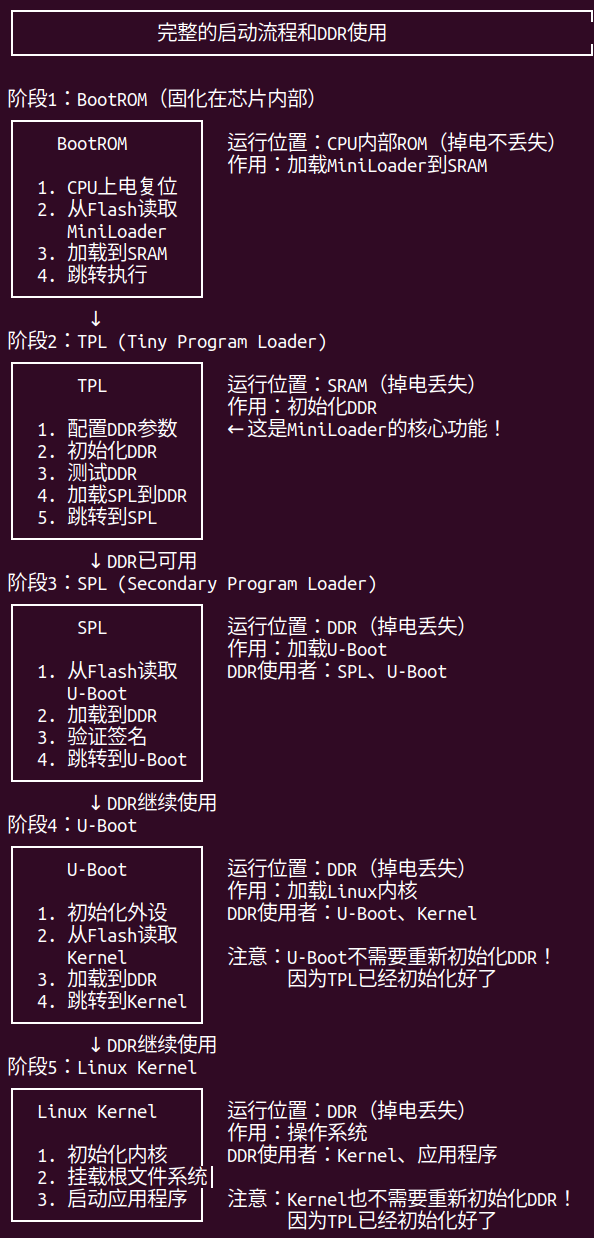
启动流程详解:
| 阶段 | 名称 | 运行位置 | 主要功能 |
|---|---|---|---|
| 1 | TPL (Tiny Program Loader) | SRAM | 初始化DDR内存 |
| 2 | SPL (Secondary Program Loader) | DDR | 加载U-Boot |
| 3 | U-Boot | DDR | 初始化硬件、加载内核 |
| 4 | Linux Kernel | DDR | 操作系统内核 |
| 5 | RootFS | DDR | 根文件系统 |
1.2 U-Boot的核心职责
1. 硬件初始化
U-Boot负责初始化系统启动所需的所有硬件设备:
// U-Boot初始化的硬件模块
├── CPU和时钟系统
│   ├── CPU频率配置
│   ├── 系统时钟树配置
│   └── 电源管理单元(PMU)
│
├── 内存控制器
│   ├── DDR参数配置
│   ├── 内存时序调整
│   └── 内存测试
│
├── 串口(UART)
│   ├── 波特率配置
│   ├── 调试输出
│   └── 命令行交互
│
├── 存储设备
│   ├── eMMC控制器
│   ├── SPI Flash控制器
│   └── SD卡控制器
│
├── 网络接口
│   ├── 以太网MAC
│   ├── PHY芯片
│   └── TFTP启动支持
│
└── 其他外设
    ├── GPIO
    ├── I2C
    ├── SPI
    └── USB
2. 加载内核
U-Boot的主要任务是加载并启动Linux内核:
┌─────────────────────────────────────────────────────────┐
│              U-Boot加载内核流程                           │
└─────────────────────────────────────────────────────────┘

1. 读取boot分区
   ├─ 从eMMC/SPI Flash读取boot.img
   └─ boot.img是FIT格式镜像

2. 解析FIT镜像
   ├─ 提取内核镜像(Image)
   ├─ 提取设备树(DTB)
   └─ 提取资源镜像(resource.img)

3. 加载到内存
   ├─ 内核加载到0x40000000
   ├─ DTB加载到0x41000000
   └─ Ramdisk加载到0x42000000(如果有)

4. 设置启动参数
   ├─ bootargs环境变量
   ├─ 内核命令行参数
   └─ 设备树地址

5. 跳转到内核
   └─ 执行bootm命令启动内核
关键环境变量:
# 查看U-Boot环境变量
=> printenv

# 重要的环境变量
bootargs=console=ttyFIQ0,1500000n8 root=/dev/mmcblk0p7 rootwait rw
bootcmd=mmc dev 0; mmc read 0x40000000 0x8000 0x10000; bootm 0x40000000
bootdelay=3
3. 提供交互环境
U-Boot提供了一个命令行界面,用于:
- 调试硬件 - 读写内存、GPIO、寄存器
- 测试功能 - 测试存储、网络、USB等
- 手动启动 - 手动加载和启动内核
- 固件升级 - 通过网络或USB升级固件
常用命令分类:
| 类别 | 命令 | 说明 |
|---|---|---|
| 信息查看 | version |
查看U-Boot版本 |
bdinfo |
查看板级信息 | |
printenv |
查看环境变量 | |
| 内存操作 | md |
显示内存内容 |
mm |
修改内存 | |
mw |
写入内存 | |
cp |
复制内存 | |
| 存储操作 | mmc list |
列出MMC设备 |
mmc dev |
选择MMC设备 | |
mmc read |
读取MMC | |
mmc write |
写入MMC | |
| 网络操作 | ping |
测试网络连通性 |
dhcp |
获取IP地址 | |
tftp |
TFTP下载文件 | |
| 启动操作 | boot |
启动系统 |
bootm |
启动内核镜像 | |
reset |
重启系统 |
4. 启动模式选择
U-Boot支持多种启动模式:
┌─────────────────────────────────────────────────────────┐
│              U-Boot启动模式                               │
└─────────────────────────────────────────────────────────┘

1. 正常启动模式 (Normal Boot)
   ├─ 加载boot分区的内核
   ├─ 挂载rootfs分区
   └─ 启动正常系统

2. Recovery模式
   ├─ 加载recovery分区的内核
   ├─ 挂载recovery ramdisk
   └─ 用于系统恢复和升级

3. Fastboot模式
   ├─ 进入USB Fastboot协议
   ├─ 用于快速烧录固件
   └─ 支持分区擦除、写入

4. 网络启动模式 (TFTP Boot)
   ├─ 通过TFTP下载内核
   ├─ 通过NFS挂载根文件系统
   └─ 用于开发调试

5. USB启动模式
   ├─ 从USB存储设备启动
   └─ 用于系统恢复
启动模式切换方法:
# 方法1:通过misc分区控制
# Android/Linux系统写入BCB数据到misc分区
# U-Boot读取misc分区决定启动模式

# 方法2:通过按键组合
# 上电时按住特定按键进入Recovery

# 方法3:通过U-Boot命令
=> setenv bootcmd "run recoveryboot"
=> saveenv
=> reset
1.3 U-Boot在RV1126B平台的特点
RV1126B的U-Boot配置文件
# U-Boot配置文件位置
/home/alientek/atk_dlrv1126b_linux6.1_sdk/u-boot/configs/

# 正点原子的配置
alientek_rv1126b_defconfig          # 正点原子标准配置

# Rockchip官方配置
rv1126b_defconfig                   # RV1126B基础配置
rv1126b-emmc-fastboot_defconfig     # eMMC + Fastboot
rv1126b-spi-nor_defconfig           # SPI NOR Flash
rv1126b-spi-nand-fastboot_defconfig # SPI NAND + Fastboot
二、U-Boot移植步骤
2.1 移植前的准备工作
1. 了解硬件差异
在开始移植之前,需要明确硬件与参考板的差异
如何获取硬件信息:
# 1. 查看原理图
# 对比你的原理图和正点原子的原理图

# 2. 查看现有设备树
cd /home/alientek/atk_dlrv1126b_linux6.1_sdk/u-boot/arch/arm/dts/
cat rv1126b-alientek.dts

# 3. 查看现有配置
cd /home/alientek/atk_dlrv1126b_linux6.1_sdk/u-boot/configs/
cat alientek_rv1126b_defconfig
2. 准备开发环境
# 确保SDK已经完整编译过一次
cd /home/alientek/atk_dlrv1126b_linux6.1_sdk
./build.sh

# 进入U-Boot目录
cd u-boot

# 查看当前配置
ls -l .config
ls -l defconfig
3. 备份原始文件
# 备份重要文件
cp configs/alientek_rv1126b_defconfig configs/alientek_rv1126b_defconfig.bak
cp arch/arm/dts/rv1126-alientek-dlrv1126b.dts arch/arm/dts/rv1126-alientek-dlrv1126b.dts.bak
2.2 第1步:创建板级配置文件
如果你的硬件与正点原子的板子有差异,建议创建自己的配置文件:
方法1:复制现有配置
cd /home/alientek/atk_dlrv1126b_linux6.1_sdk/u-boot

# 复制配置文件
cp configs/alientek_rv1126b_defconfig configs/my_rv1126b_defconfig

# 编辑配置文件
vim configs/my_rv1126b_defconfig
方法2:通过menuconfig创建
# 加载基础配置
make alientek_rv1126b_defconfig

# 图形化配置界面
make menuconfig

# 保存配置
make savedefconfig

# 移动到configs目录
mv defconfig configs/my_rv1126b_defconfig
defconfig文件示例:
# configs/my_rv1126b_defconfig

CONFIG_ARM=y
CONFIG_ARCH_ROCKCHIP=y
CONFIG_SPL_LIBCOMMON_SUPPORT=y
CONFIG_SPL_LIBGENERIC_SUPPORT=y
CONFIG_SYS_MALLOC_F_LEN=0x2000
CONFIG_ROCKCHIP_RV1126=y
CONFIG_ROCKCHIP_SPL_RESERVE_IRAM=0x0
CONFIG_TARGET_RV1126_RV1109=y
CONFIG_SPL_STACK_R_ADDR=0x600000
CONFIG_DEFAULT_DEVICE_TREE="rv1126-my-board"  # 修改设备树名称
CONFIG_DEBUG_UART=y
CONFIG_FIT=y
CONFIG_FIT_VERBOSE=y
CONFIG_SPL_LOAD_FIT=y
# ... 更多配置
2.3 第2步:修改设备树(DTS)
设备树(Device Tree)是描述硬件信息的文件,U-Boot和Linux内核都会使用它。
设备树文件位置
cd /home/alientek/atk_dlrv1126b_linux6.1_sdk/u-boot/arch/arm/dts/

# 查看RV1126相关的设备树
ls -l rv1126*.dts*

# 主要文件
rv1126.dtsi                          # RV1126芯片级设备树(基础)
rv1126-alientek-dlrv1126b.dts        # 正点原子板级设备树
rv1126-alientek-dlrv1126b-*.dtsi     # 正点原子板级设备树片段
创建自己的设备树
# 复制正点原子的设备树
cp rv1126-alientek-dlrv1126b.dts rv1126-my-board.dts

# 编辑设备树
vim rv1126-my-board.dts
设备树基本结构
/dts-v1/;
#include "rv1126.dtsi"
#include "rv1126-my-board-camera.dtsi"  // 摄像头配置
#include "rv1126-my-board-display.dtsi" // 显示配置

/ {
    model = "My RV1126B Board";
    compatible = "my-company,rv1126b", "rockchip,rv1126";

    chosen {
        stdout-path = "serial2:1500000n8";  // 调试串口
    };

    // 板级配置
    // ...
};

// 外设配置
&uart2 {
    status = "okay";
};

&i2c0 {
    status = "okay";
    clock-frequency = <400000>;

    // I2C设备
};

// 更多外设配置...
常见修改项详解
1. GPIO配置
// 修改LED GPIO
&gpio0 {
    status = "okay";
};

/ {
    leds {
        compatible = "gpio-leds";

        led_power {
            label = "power_led";
            gpios = <&gpio0 RK_PA0 GPIO_ACTIVE_HIGH>;
            default-state = "on";
        };

        led_status {
            label = "status_led";
            gpios = <&gpio0 RK_PA1 GPIO_ACTIVE_HIGH>;
            linux,default-trigger = "heartbeat";
        };
    };

    gpio-keys {
        compatible = "gpio-keys";
        autorepeat;

        power-key {
            label = "Power Key";
            gpios = <&gpio0 RK_PA5 GPIO_ACTIVE_LOW>;
            linux,code = <KEY_POWER>;
            wakeup-source;
        };
    };
};
2. I2C设备配置(陀螺仪)
&i2c2 {
    status = "okay";
    clock-frequency = <400000>;

    icm20948: icm20948@68 {
        compatible = "invensense,icm20948";
        reg = <0x68>;
        interrupt-parent = <&gpio0>;
        interrupts = <RK_PB0 IRQ_TYPE_EDGE_RISING>;

        // 陀螺仪配置
        gyro-range = <250>;  // ±250°/s
        accel-range = <2>;   // ±2g
    };
};
3. SPI设备配置
&spi0 {
    status = "okay";
    max-freq = <48000000>;

    spiflash: spi-flash@0 {
        compatible = "jedec,spi-nor";
        reg = <0>;
        spi-max-frequency = <48000000>;

        partitions {
            compatible = "fixed-partitions";
            #address-cells = <1>;
            #size-cells = <1>;

            partition@0 {
                label = "bootloader";
                reg = <0x0 0x100000>;
            };

            partition@100000 {
                label = "env";
                reg = <0x100000 0x10000>;
            };
        };
    };
};
4. MIPI屏幕配置
&dsi {
    status = "okay";

    panel@0 {
        compatible = "simple-panel-dsi";
        reg = <0>;
        backlight = <&backlight>;
        power-supply = <&vcc_lcd>;
        reset-gpios = <&gpio0 RK_PC0 GPIO_ACTIVE_LOW>;

        display-timings {
            native-mode = <&timing0>;

            timing0: timing0 {
                clock-frequency = <65000000>;
                hactive = <720>;
                vactive = <1280>;
                hfront-porch = <20>;
                hsync-len = <10>;
                hback-porch = <20>;
                vfront-porch = <10>;
                vsync-len = <4>;
                vback-porch = <10>;
                hsync-active = <0>;
                vsync-active = <0>;
                de-active = <0>;
                pixelclk-active = <0>;
            };
        };

        port {
            panel_in_dsi: endpoint {
                remote-endpoint = <&dsi_out_panel>;
            };
        };
    };
};

&dsi_in_vop {
    status = "okay";
};

&dsi_out_panel {
    status = "okay";
};

&route_dsi {
    status = "okay";
};
5. USB配置(5G模组)
&usb_host0_ehci {
    status = "okay";
};

&usb_host0_ohci {
    status = "okay";
};

&usb2phy0 {
    status = "okay";

    usb2phy0_host: host-port {
        status = "okay";
    };
};

// 5G模组电源控制
/ {
    vcc_5g: vcc-5g-regulator {
        compatible = "regulator-fixed";
        regulator-name = "vcc_5g";
        gpio = <&gpio0 RK_PA3 GPIO_ACTIVE_HIGH>;
        enable-active-high;
        regulator-always-on;
        regulator-boot-on;
    };
};
6. SDIO配置(WiFi模组)
&sdio {
    status = "okay";
    max-frequency = <150000000>;
    bus-width = <4>;
    cap-sd-highspeed;
    cap-sdio-irq;
    keep-power-in-suspend;
    non-removable;
    rockchip,default-sample-phase = <90>;
    sd-uhs-sdr104;

    // WiFi模组
    wifi@1 {
        compatible = "realtek,rtl8733bs";
        reg = <1>;
        interrupt-parent = <&gpio0>;
        interrupts = <RK_PA6 IRQ_TYPE_LEVEL_HIGH>;
    };
};

// WiFi电源控制
/ {
    sdio_pwrseq: sdio-pwrseq {
        compatible = "mmc-pwrseq-simple";
        reset-gpios = <&gpio0 RK_PA4 GPIO_ACTIVE_LOW>;
        post-power-on-delay-ms = <200>;
    };
};

&sdio {
    mmc-pwrseq = <&sdio_pwrseq>;
};
7. eMMC配置
&emmc {
    status = "okay";
    bus-width = <8>;
    cap-mmc-highspeed;
    mmc-hs200-1_8v;
    supports-emmc;
    non-removable;
    rockchip,default-sample-phase = <90>;
};
设备树编译
修改设备树后,需要重新编译:
# 方法1:单独编译设备树
cd /home/alientek/atk_dlrv1126b_linux6.1_sdk/u-boot
make rv1126-my-board.dtb

# 方法2:编译整个U-Boot(会自动编译设备树)
make -j$(nproc)

# 查看编译后的设备树
ls -l arch/arm/dts/rv1126-my-board.dtb
设备树调试技巧
# 1. 反编译设备树查看
dtc -I dtb -O dts -o output.dts arch/arm/dts/rv1126-my-board.dtb

# 2. 查看设备树中的某个节点
fdtget arch/arm/dts/rv1126-my-board.dtb /chosen stdout-path

# 3. 在U-Boot中查看设备树
=> fdt addr ${fdtcontroladdr}
=> fdt print /
=> fdt print /chosen
2.4 第3步:修改板级代码
如果需要添加自定义的硬件初始化代码,需要修改板级文件。
板级代码位置
cd /home/alientek/atk_dlrv1126b_linux6.1_sdk/u-boot/board/rockchip/evb_rv1126b/

# 主要文件
ls -l
# evb_rv1126b.c  - 板级初始化代码
# Kconfig          - 配置选项
# MAINTAINERS      - 维护者信息
# Makefile         - 编译规则
板级初始化代码示例
// board/rockchip/rv1126_rv1109/rv1126-rv1109.c

#include <common.h>
#include <dm.h>
#include <asm/io.h>
#include <asm/arch/hardware.h>
#include <asm/gpio.h>

DECLARE_GLOBAL_DATA_PTR;

// 板级早期初始化(在DDR初始化之前)
int board_early_init_f(void)
{
    // 配置关键GPIO
    // 例如:电源使能、复位信号等

    return 0;
}

// 板级初始化(在DDR初始化之后)
int board_init(void)
{
    printf("Board: My RV1126B Board\n");

    // 初始化5G模组
    init_5g_module();

    // 初始化WiFi模组
    init_wifi_module();

    // 初始化其他硬件
    init_other_hardware();

    return 0;
}

// 5G模组初始化
static int init_5g_module(void)
{
    int ret;

    printf("Initializing 5G module (RM500Q)...\n");

    // 1. 配置5G模组电源GPIO
    ret = gpio_request(GPIO_5G_POWER, "5g_power");
    if (ret) {
        printf("Failed to request 5G power GPIO\n");
        return ret;
    }

    // 2. 使能5G模组电源
    gpio_direction_output(GPIO_5G_POWER, 1);
    mdelay(100);  // 等待电源稳定

    // 3. 配置5G模组复位GPIO
    ret = gpio_request(GPIO_5G_RESET, "5g_reset");
    if (ret) {
        printf("Failed to request 5G reset GPIO\n");
        return ret;
    }

    // 4. 复位5G模组
    gpio_direction_output(GPIO_5G_RESET, 0);
    mdelay(10);
    gpio_direction_output(GPIO_5G_RESET, 1);
    mdelay(100);

    printf("5G module initialized\n");
    return 0;
}

// WiFi模组初始化
static int init_wifi_module(void)
{
    int ret;

    printf("Initializing WiFi module (RTL8733)...\n");

    // 1. 配置WiFi电源GPIO
    ret = gpio_request(GPIO_WIFI_POWER, "wifi_power");
    if (ret) {
        printf("Failed to request WiFi power GPIO\n");
        return ret;
    }

    // 2. 使能WiFi电源
    gpio_direction_output(GPIO_WIFI_POWER, 1);
    mdelay(50);

    // 3. 配置WiFi复位GPIO
    ret = gpio_request(GPIO_WIFI_RESET, "wifi_reset");
    if (ret) {
        printf("Failed to request WiFi reset GPIO\n");
        return ret;
    }

    // 4. 复位WiFi模组
    gpio_direction_output(GPIO_WIFI_RESET, 0);
    mdelay(10);
    gpio_direction_output(GPIO_WIFI_RESET, 1);
    mdelay(100);

    printf("WiFi module initialized\n");
    return 0;
}

// 板级晚期初始化
int board_late_init(void)
{
    // 设置环境变量
    env_set("board_name", "my_rv1126b");
    env_set("board_rev", "v1.0");

    // 检测启动模式
    check_boot_mode();

    return 0;
}

// 检测启动模式
static void check_boot_mode(void)
{
    // 读取按键状态
    int recovery_key = gpio_get_value(GPIO_RECOVERY_KEY);

    if (recovery_key == 0) {
        printf("Recovery key pressed, entering recovery mode\n");
        env_set("bootcmd", "run recoveryboot");
    }
}

// 显示板级信息
int checkboard(void)
{
    printf("Board: My RV1126B Board v1.0\n");
    printf("CPU:   Rockchip RV1126B\n");
    printf("Model: 5G/WiFi Law Enforcement Recorder\n");

    return 0;
}
GPIO定义
在头文件中定义GPIO:
// board/rockchip/rv1126_rv1109/rv1126-rv1109.h

#ifndef __RV1126_RV1109_H
#define __RV1126_RV1109_H

// GPIO定义
#define GPIO_5G_POWER       GPIO0_A3
#define GPIO_5G_RESET       GPIO0_A4
#define GPIO_WIFI_POWER     GPIO0_A5
#define GPIO_WIFI_RESET     GPIO0_A6
#define GPIO_RECOVERY_KEY   GPIO0_B0

// 其他定义
// ...

#endif
2.5 第4步:配置U-Boot功能
使用menuconfig配置U-Boot的功能选项。
启动menuconfig
cd /home/alientek/atk_dlrv1126b_linux6.1_sdk/u-boot

# 加载配置
make alientek_rv1126b_defconfig

# 启动图形化配置
make menuconfig
常用配置项
1. 设备驱动配置
Device Drivers  --->
    [*] GPIO Support  --->
        [*] Rockchip GPIO driver

    [*] I2C Support  --->
        [*] Rockchip I2C driver

    [*] SPI Support  --->
        [*] Rockchip SPI driver

    [*] MMC Support  --->
        [*] Rockchip SD/MMC controller support
        [*] Rockchip SDHCI controller support

    [*] USB Support  --->
        [*] USB Host Controller Drivers
        [*] EHCI HCD (USB 2.0) support
        [*] OHCI HCD (USB 1.1) support
        [*] USB Gadget Support  --->
            [*] USB Gadget Download support
            [*] USB Fastboot support

    [*] Network device support  --->
        [*] Ethernet driver support
        [*] Realtek PHY support

    [*] Video support  --->
        [*] Enable Rockchip Video Support
        [*] Rockchip MIPI DSI support
2. 命令行配置
Command line interface  --->
    [*] Network commands  --->
        [*] bootp, tftpboot
        [*] dhcp
        [*] ping
        [*] tftp

    [*] Device access commands  --->
        [*] i2c
        [*] gpio
        [*] mmc
        [*] usb

    [*] Memory commands  --->
        [*] md, mm, nm, mw, cp, cmp, base, loop
        [*] memtest

    [*] Filesystem commands  --->
        [*] ext2 command support
        [*] ext4 command support
        [*] fat command support
3. 启动选项配置
Boot options  --->
    (3) delay in seconds before automatically booting
    [*] Enable a default value for bootcmd
    (mmc dev 0; mmc read 0x40000000 0x8000 0x10000; bootm 0x40000000) bootcmd value

    [*] Enable boot arguments
    (console=ttyFIQ0,1500000n8 root=/dev/mmcblk0p7 rootwait rw) Boot arguments

    [*] Support for booting from FIT image
    [*] Enable signature verification of FIT images
4. 环境变量配置
Environment  --->
    [*] Environment in MMC
    (0) Device number for MMC
    (0x1f8000) Offset for environment in MMC
    (0x8000) Size of environment in MMC
保存配置
# 保存配置到defconfig
make savedefconfig

# 移动到configs目录
mv defconfig configs/my_rv1126b_defconfig

# 或者直接保存到.config
# 下次编译时会使用.config
2.6 第5步:编译U-Boot
完成配置后,开始编译U-Boot。
编译方法
# 方法1:使用SDK的build.sh脚本(推荐)
cd /home/alientek/atk_dlrv1126b_linux6.1_sdk
./build.sh uboot

# 方法2:单独编译U-Boot
cd /home/alientek/atk_dlrv1126b_linux6.1_sdk/u-boot

# 清理之前的编译
make clean

# 加载配置
make alientek_rv1126b_defconfig
# 或使用自己的配置
# make my_rv1126b_defconfig

# 编译(使用多核加速)
make -j$(nproc)

# 查看编译进度
# 编译时间约5-10分钟
编译产物
# 编译完成后,查看生成的文件
ls -lh uboot.img
ls -lh u-boot.bin
ls -lh u-boot.dtb

# 主要产物说明
uboot.img           # 最终的U-Boot镜像(FIT格式)
                    # 包含:u-boot.bin + trust.img + u-boot.dtb

u-boot.bin          # U-Boot二进制文件
u-boot.dtb          # U-Boot设备树
u-boot              # U-Boot ELF文件(用于调试)
u-boot.map          # 符号表文件
编译错误处理
常见编译错误:
- 设备树编译错误
# 错误信息
Error: arch/arm/dts/rv1126-my-board.dts:123: syntax error

# 解决方法
# 检查设备树语法,确保括号、分号正确
vim arch/arm/dts/rv1126-my-board.dts
- 缺少头文件
# 错误信息
fatal error: xxx.h: No such file or directory

# 解决方法
# 检查include路径,确保头文件存在
find . -name "xxx.h"
- 链接错误
# 错误信息
undefined reference to `xxx'

# 解决方法
# 检查函数定义,确保相关代码已编译
grep -r "xxx" .
2.7 第6步:烧录和测试
编译完成后,将U-Boot烧录到开发板进行测试。
烧录方法
方法1:使用RKDevTool(Windows)
1. 打开RKDevTool工具
2. 开发板进入Maskrom模式或Loader模式
3. 选择"下载镜像"标签
4. 勾选"uboot"分区
5. 选择uboot.img文件
6. 点击"执行"按钮
方法2:使用upgrade_tool(Linux)
# 安装upgrade_tool
cd /home/alientek/atk_dlrv1126b_linux6.1_sdk/tools/linux/Linux_Upgrade_Tool
sudo ./upgrade_tool

# 查看设备
sudo ./upgrade_tool ld

# 烧录U-Boot到uboot分区
sudo ./upgrade_tool di -u /path/to/uboot.img

# 或者烧录完整固件
cd /home/alientek/atk_dlrv1126b_linux6.1_sdk
./build.sh firmware
sudo ./tools/linux/Linux_Upgrade_Tool/upgrade_tool uf rockdev/update.img
方法3:通过U-Boot命令烧录(高级)
# 如果U-Boot已经可以启动,可以通过TFTP更新
=> setenv serverip 192.168.1.100
=> setenv ipaddr 192.168.1.10
=> tftp 0x40000000 uboot.img
=> mmc dev 0
=> mmc write 0x40000000 0x4000 0x2000
=> reset
测试步骤
1. 连接串口
# 连接串口(波特率1500000)
sudo minicom -D /dev/ttyUSB0 -b 1500000

# 或使用screen
sudo screen /dev/ttyUSB0 1500000

# 或使用picocom
sudo picocom -b 1500000 /dev/ttyUSB0
2. 上电启动
# 正常启动日志示例
DDR Version V1.08 20210810
LPDDR3, 528MHz
BW=32 Col=10 Bk=8 CS0 Row=15 CS1 Row=15 CS=2 Die BW=16 Size=1024MB

U-Boot 2017.09 (Feb 01 2025 - 14:20:00 +0800)

Model: My RV1126B Board v1.0
DRAM:  1 GiB
Relocation Offset is: 3dee0000
Initializing 5G module (RM500Q)...
5G module initialized
Initializing WiFi module (RTL8733)...
WiFi module initialized
MMC:   dwmmc@ffc50000: 0
Loading Environment from MMC... OK
In:    serial@ff560000
Out:   serial@ff560000
Err:   serial@ff560000
Model: My RV1126B Board v1.0
Net:   No ethernet found.
Hit any key to stop autoboot:  3
=>
3. 测试基本功能
# 测试1:查看版本信息
=> version
U-Boot 2017.09 (Feb 01 2025 - 14:20:00 +0800)

# 测试2:查看板级信息
=> bdinfo
arch_number = 0x00000000
boot_params = 0x40000100
DRAM bank   = 0x00000000
-> start    = 0x40000000
-> size     = 0x40000000

# 测试3:查看环境变量
=> printenv
bootargs=console=ttyFIQ0,1500000n8 root=/dev/mmcblk0p7 rootwait rw
bootcmd=mmc dev 0; mmc read 0x40000000 0x8000 0x10000; bootm 0x40000000
bootdelay=3

# 测试4:测试MMC
=> mmc list
dwmmc@ffc50000: 0

=> mmc dev 0
switch to partitions #0, OK
mmc0 is current device

=> mmc info
Device: dwmmc@ffc50000
Manufacturer ID: 15
OEM: 100
Name: 8GTF4
Bus Speed: 52000000
Mode : MMC High Speed (52MHz)
Rd Block Len: 512
MMC version 5.1
High Capacity: Yes
Capacity: 7.3 GiB

# 测试5:测试GPIO
=> gpio status
Bank gpio0:
gpio0_0: input: 0 [ ]
gpio0_1: input: 0 [ ]
gpio0_2: input: 0 [ ]
gpio0_3: output: 1 [x] 5g_power

# 测试6:读取内存
=> md.l 0x40000000 0x10
40000000: 00000000 00000000 00000000 00000000    ................
40000010: 00000000 00000000 00000000 00000000    ................
40000020: 00000000 00000000 00000000 00000000    ................
40000030: 00000000 00000000 00000000 00000000    ................

# 测试7:手动启动内核
=> mmc dev 0
=> mmc read 0x40000000 0x8000 0x10000
=> bootm 0x40000000
4. 测试启动模式
# 测试正常启动
=> boot

# 测试Recovery模式
=> setenv bootcmd "run recoveryboot"
=> saveenv
=> reset

# 测试Fastboot模式
=> fastboot usb 0
2.8 第7步:调试和优化
如果启动有问题,需要进行调试。
常见问题排查
问题1:U-Boot无法启动
现象: 串口无输出或输出乱码
排查步骤:
# 1. 检查串口连接
# - 确认串口线连接正确
# - 确认波特率设置为1500000

# 2. 检查U-Boot镜像
# - 确认uboot.img烧录成功
# - 确认烧录到正确的分区

# 3. 检查DDR配置
# - DDR参数是否正确
# - DDR初始化是否成功
问题2:设备树加载失败
现象: 提示"Failed to load device tree"
排查步骤:
# 1. 检查设备树编译
cd u-boot
make rv1126-my-board.dtb

# 2. 检查设备树语法
dtc -I dtb -O dts -o output.dts arch/arm/dts/rv1126-my-board.dtb

# 3. 在U-Boot中查看设备树
=> fdt addr ${fdtcontroladdr}
=> fdt print /
问题3:外设无法工作
现象: GPIO、I2C、SPI等外设不工作
排查步骤:
# 1. 检查设备树配置
# - 确认外设节点status = "okay"
# - 确认GPIO配置正确

# 2. 检查驱动是否启用
# - 在menuconfig中确认驱动已选中

# 3. 添加调试打印
# 在驱动代码中添加printf调试
问题4:内核无法启动
现象: U-Boot正常,但无法启动内核
排查步骤:
# 1. 检查boot分区
=> mmc dev 0
=> mmc read 0x40000000 0x8000 0x10000
=> iminfo 0x40000000

# 2. 检查bootargs
=> printenv bootargs
# 确认root分区、console等参数正确

# 3. 手动启动内核
=> bootm 0x40000000
# 查看启动日志
性能优化
1. 减少启动延迟
# 修改bootdelay
=> setenv bootdelay 1
=> saveenv

# 或在defconfig中修改
CONFIG_BOOTDELAY=1
2. 并行初始化
// 在board_init()中使用并行初始化
int board_init(void)
{
    // 启动初始化线程
    start_init_thread(init_5g_module);
    start_init_thread(init_wifi_module);

    // 等待初始化完成
    wait_init_complete();

    return 0;
}
3. 禁用不需要的功能
# 在menuconfig中禁用不需要的命令和驱动
# 减小U-Boot体积,加快启动速度
三、U-Boot调试方法
3.1 串口调试(最常用)
串口是U-Boot调试的主要方法,几乎所有问题都可以通过串口日志定位。
连接串口
# 方法1:使用minicom
sudo minicom -D /dev/ttyUSB0 -b 1500000

# minicom配置
# Ctrl+A -> Z -> O -> Serial port setup
# A - Serial Device      : /dev/ttyUSB0
# E - Bps/Par/Bits       : 1500000 8N1
# F - Hardware Flow Control : No
# G - Software Flow Control : No

# 方法2:使用screen
sudo screen /dev/ttyUSB0 1500000

# 方法3:使用picocom
sudo picocom -b 1500000 /dev/ttyUSB0

# 方法4:使用putty(Windows)
# 配置串口参数:
# Speed: 1500000
# Data bits: 8
# Stop bits: 1
# Parity: None
# Flow control: None
U-Boot命令详解
信息查看命令
# 查看U-Boot版本
=> version
U-Boot 2017.09 (Feb 01 2025 - 14:20:00 +0800)
arm-linux-gnueabihf-gcc (Linaro GCC 7.3-2018.05) 7.3.1 20180425
GNU ld (Linaro_Binutils-2018.05) 2.28.2.20170706

# 查看板级信息
=> bdinfo
arch_number = 0x00000000
boot_params = 0x40000100
DRAM bank   = 0x00000000
-> start    = 0x40000000
-> size     = 0x40000000
baudrate    = 1500000 bps
TLB addr    = 0x7FFF0000
relocaddr   = 0x7DF20000
reloc off   = 0x3DF20000
irq_sp      = 0x7CEFF6E0
sp start    = 0x7CEFF6D0

# 查看环境变量
=> printenv
bootargs=console=ttyFIQ0,1500000n8 root=/dev/mmcblk0p7 rootwait rw
bootcmd=mmc dev 0; mmc read 0x40000000 0x8000 0x10000; bootm 0x40000000
bootdelay=3
baudrate=1500000
ethaddr=00:11:22:33:44:55

# 查看单个环境变量
=> printenv bootargs
bootargs=console=ttyFIQ0,1500000n8 root=/dev/mmcblk0p7 rootwait rw
内存操作命令
# 显示内存内容(字节)
=> md.b 0x40000000 0x100

# 显示内存内容(半字)
=> md.w 0x40000000 0x80

# 显示内存内容(字)
=> md.l 0x40000000 0x40
40000000: 00000000 00000000 00000000 00000000    ................
40000010: 00000000 00000000 00000000 00000000    ................

# 修改内存(交互式)
=> mm.l 0x40000000
40000000: 00000000 ? 12345678
40000004: 00000000 ? q

# 写入内存
=> mw.l 0x40000000 0x12345678 0x10

# 复制内存
=> cp.l 0x40000000 0x41000000 0x1000

# 比较内存
=> cmp.l 0x40000000 0x41000000 0x1000

# 内存测试
=> mtest 0x40000000 0x50000000
Pattern 00000000  Writing...  Reading...
MMC/SD卡操作命令
# 列出MMC设备
=> mmc list
dwmmc@ffc50000: 0

# 选择MMC设备
=> mmc dev 0
switch to partitions #0, OK
mmc0 is current device

# 查看MMC信息
=> mmc info
Device: dwmmc@ffc50000
Manufacturer ID: 15
OEM: 100
Name: 8GTF4
Bus Speed: 52000000
Mode : MMC High Speed (52MHz)
Rd Block Len: 512
MMC version 5.1
High Capacity: Yes
Capacity: 7.3 GiB

# 查看MMC分区
=> mmc part

Partition Map for MMC device 0  --   Partition Type: EFI

Part    Start LBA       End LBA         Name
        Attributes
        Type GUID
        Partition GUID
  1     0x00004000      0x00005fff      "uboot"
        attrs:  0x0000000000000000
        type:   ebd0a0a2-b9e5-4433-87c0-68b6b72699c7
        guid:   b3e3e3e3-e3e3-e3e3-e3e3-e3e3e3e3e3e3

# 读取MMC
=> mmc read 0x40000000 0x8000 0x10000
MMC read: dev # 0, block # 32768, count 65536 ... 65536 blocks read: OK

# 写入MMC
=> mmc write 0x40000000 0x8000 0x10000
MMC write: dev # 0, block # 32768, count 65536 ... 65536 blocks written: OK

# 擦除MMC
=> mmc erase 0x8000 0x10000
MMC erase: dev # 0, block # 32768, count 65536 ... 65536 blocks erased: OK
GPIO操作命令
# 查看GPIO状态
=> gpio status
Bank gpio0:
gpio0_0: input: 0 [ ]
gpio0_1: input: 0 [ ]
gpio0_2: input: 0 [ ]
gpio0_3: output: 1 [x] 5g_power
gpio0_4: output: 1 [x] 5g_reset

# 设置GPIO为输出
=> gpio set 0
=> gpio clear 0

# 读取GPIO输入
=> gpio input 0
gpio: pin 0 (gpio 0) value is 1

# 切换GPIO
=> gpio toggle 0
I2C操作命令
# 扫描I2C总线
=> i2c dev 0
Setting bus to 0
=> i2c probe
Valid chip addresses: 68

# 读取I2C设备
=> i2c md 0x68 0x75 1
0075: 71

# 写入I2C设备
=> i2c mw 0x68 0x6b 0x00 1

# 连续读取
=> i2c md 0x68 0x00 0x10
0000: 71 00 00 00 00 00 00 00 00 00 00 00 00 00 00 00    q...............
网络操作命令
# 设置IP地址
=> setenv ipaddr 192.168.1.10
=> setenv serverip 192.168.1.100
=> setenv netmask 255.255.255.0
=> setenv gatewayip 192.168.1.1

# 测试网络连通性
=> ping 192.168.1.100
Using ethernet@ffc40000 device
host 192.168.1.100 is alive

# DHCP获取IP
=> dhcp
BOOTP broadcast 1
DHCP client bound to address 192.168.1.10 (5 ms)

# TFTP下载文件
=> tftp 0x40000000 uImage
Using ethernet@ffc40000 device
TFTP from server 192.168.1.100; our IP address is 192.168.1.10
Filename 'uImage'.
Load address: 0x40000000
Loading: #################################################################
         #################################################################
         done
Bytes transferred = 4567890 (45b2d2 hex)

# TFTP上传文件
=> tftpput 0x40000000 0x100000 uboot.img
启动相关命令
# 启动系统
=> boot

# 从内存启动内核
=> bootm 0x40000000

# 从FIT镜像启动
=> bootm 0x40000000#config@1

# 重启系统
=> reset

# 进入Fastboot模式
=> fastboot usb 0
3.2 添加调试打印
在U-Boot源码中添加调试信息是最直接的调试方法。
基本调试打印
// 在任何C文件中添加
#include <common.h>

void my_debug_function(void)
{
    // 普通打印(总是输出)
    printf("Debug: Entering my_debug_function\n");
    printf("GPIO0 value: 0x%08x\n", readl(GPIO0_BASE));

    // 详细调试打印(只在定义DEBUG时输出)
    debug("This only prints if DEBUG is defined\n");
    debug("Variable x = %d\n", x);

    // 错误打印
    pr_err("Error occurred: %d\n", error_code);

    // 警告打印
    pr_warn("Warning: something wrong\n");

    // 信息打印
    pr_info("Info: initialization complete\n");
}
启用调试输出
// 方法1:在文件开头定义DEBUG
#define DEBUG
#include <common.h>

// 方法2:在Makefile中添加
CFLAGS_xxx.o := -DDEBUG

// 方法3:在defconfig中启用
CONFIG_LOG=y
CONFIG_LOGLEVEL=7
调试宏定义
// 常用调试宏
#define DBG(fmt, args...) \
    printf("[%s:%d] " fmt, __func__, __LINE__, ##args)

#define DBG_HERE() \
    printf("[%s:%d] Here!\n", __func__, __LINE__)

#define DBG_VAR(var) \
    printf("[%s:%d] %s = 0x%x\n", __func__, __LINE__, #var, var)

// 使用示例
void test_function(void)
{
    int value = 0x12345678;

    DBG_HERE();                    // [test_function:123] Here!
    DBG("Starting test\n");        // [test_function:124] Starting test
    DBG_VAR(value);                // [test_function:125] value = 0x12345678
}
3.3 使用JTAG调试(高级)
JTAG是硬件级调试方法,可以单步调试、设置断点、查看寄存器等。
JTAG调试环境搭建
# 1. 安装OpenOCD
sudo apt-get install openocd

# 2. 安装GDB
sudo apt-get install gdb-multiarch

# 3. 准备JTAG配置文件
# 创建 rv1126.cfg
cat > rv1126.cfg << EOF
# RV1126 JTAG配置
adapter driver jlink
adapter speed 1000

transport select jtag
jtag newtap rv1126 cpu -irlen 4 -expected-id 0x0ba00477

target create rv1126.cpu cortex_a -chain-position rv1126.cpu
rv1126.cpu configure -work-area-phys 0x40000000 -work-area-size 0x10000

init
halt
EOF
启动JTAG调试
# 终端1:启动OpenOCD
openocd -f interface/jlink.cfg -f rv1126.cfg

# 终端2:启动GDB
arm-linux-gnueabihf-gdb u-boot

# GDB命令
(gdb) target remote localhost:3333
(gdb) load                          # 加载U-Boot
(gdb) break board_init              # 设置断点
(gdb) continue                      # 继续执行
(gdb) step                          # 单步执行
(gdb) next                          # 下一步
(gdb) print variable                # 打印变量
(gdb) info registers                # 查看寄存器
(gdb) backtrace                     # 查看调用栈
3.4 日志分析
正常启动日志分析
DDR Version V1.08 20210810                    # DDR初始化
LPDDR3, 528MHz                                # DDR类型和频率
BW=32 Col=10 Bk=8 CS0 Row=15 CS1 Row=15 CS=2 Die BW=16 Size=1024MB

U-Boot 2017.09 (Feb 01 2025 - 14:20:00 +0800) # U-Boot版本和编译时间

Model: My RV1126B Board v1.0                  # 板级型号
DRAM:  1 GiB                                  # 内存大小
Relocation Offset is: 3dee0000                # 重定位偏移

Initializing 5G module (RM500Q)...            # 5G模组初始化
5G module initialized
Initializing WiFi module (RTL8733)...         # WiFi模组初始化
WiFi module initialized

MMC:   dwmmc@ffc50000: 0                      # MMC设备
Loading Environment from MMC... OK            # 加载环境变量

In:    serial@ff560000                        # 输入设备
Out:   serial@ff560000                        # 输出设备
Err:   serial@ff560000                        # 错误输出设备

Model: My RV1126B Board v1.0
Net:   No ethernet found.                     # 网络设备
Hit any key to stop autoboot:  3              # 启动倒计时
异常日志分析
问题1:DDR初始化失败
DDR Version V1.08 20210810
LPDDR3, 528MHz
DDR init failed!                              # DDR初始化失败
原因: DDR参数配置错误
解决: 检查DDR配置文件
问题2:U-Boot重定位失败
U-Boot 2017.09 (Feb 01 2025 - 14:20:00 +0800)
Relocation Offset is: 3dee0000
### ERROR ### Please RESET the board ###      # 重定位失败
原因: 内存地址冲突或内存损坏
解决: 检查内存映射配置
问题3:环境变量加载失败
Loading Environment from MMC... *** Warning - bad CRC, using default environment
原因: 环境变量分区损坏或未初始化
解决: 重新保存环境变量 saveenv
四、针对执法记录仪项目的定制
4.1 5G模组初始化
U-Boot初始化代码
// board/rockchip/rv1126_rv1109/rv1126-rv1109.c

#define GPIO_5G_POWER    GPIO0_A3
#define GPIO_5G_RESET    GPIO0_A4

static int init_5g_module(void)
{
    int ret;

    printf("Initializing 5G module (RM500Q)...\n");

    // 1. 配置电源GPIO
    ret = gpio_request(GPIO_5G_POWER, "5g_power");
    if (ret) {
        pr_err("Failed to request 5G power GPIO: %d\n", ret);
        return ret;
    }

    // 2. 使能5G模组电源
    gpio_direction_output(GPIO_5G_POWER, 1);
    printf("5G power enabled\n");
    mdelay(100);  // 等待电源稳定

    // 3. 配置复位GPIO
    ret = gpio_request(GPIO_5G_RESET, "5g_reset");
    if (ret) {
        pr_err("Failed to request 5G reset GPIO: %d\n", ret);
        return ret;
    }

    // 4. 复位5G模组
    gpio_direction_output(GPIO_5G_RESET, 0);
    mdelay(10);
    gpio_direction_output(GPIO_5G_RESET, 1);
    printf("5G module reset complete\n");
    mdelay(100);

    // 5. 等待5G模组就绪
    printf("Waiting for 5G module ready...\n");
    mdelay(2000);  // RM500Q启动需要约2秒

    printf("5G module initialized successfully\n");
    return 0;
}
设备树配置
// arch/arm/dts/rv1126-my-board.dts

/ {
    // 5G模组电源
    vcc_5g: vcc-5g-regulator {
        compatible = "regulator-fixed";
        regulator-name = "vcc_5g";
        gpio = <&gpio0 RK_PA3 GPIO_ACTIVE_HIGH>;
        enable-active-high;
        regulator-boot-on;
    };
};

// USB配置(5G模组使用USB接口)
&usb_host0_ehci {
    status = "okay";
};

&usb_host0_ohci {
    status = "okay";
};

&usb2phy0 {
    status = "okay";

    usb2phy0_host: host-port {
        status = "okay";
    };
};
4.2 WiFi模组初始化
U-Boot初始化代码
#define GPIO_WIFI_POWER    GPIO0_A5
#define GPIO_WIFI_RESET    GPIO0_A6

static int init_wifi_module(void)
{
    int ret;

    printf("Initializing WiFi module (RTL8733)...\n");

    // 1. 配置WiFi电源GPIO
    ret = gpio_request(GPIO_WIFI_POWER, "wifi_power");
    if (ret) {
        pr_err("Failed to request WiFi power GPIO: %d\n", ret);
        return ret;
    }

    // 2. 使能WiFi电源
    gpio_direction_output(GPIO_WIFI_POWER, 1);
    printf("WiFi power enabled\n");
    mdelay(50);

    // 3. 配置WiFi复位GPIO
    ret = gpio_request(GPIO_WIFI_RESET, "wifi_reset");
    if (ret) {
        pr_err("Failed to request WiFi reset GPIO: %d\n", ret);
        return ret;
    }

    // 4. 复位WiFi模组
    gpio_direction_output(GPIO_WIFI_RESET, 0);
    mdelay(10);
    gpio_direction_output(GPIO_WIFI_RESET, 1);
    printf("WiFi module reset complete\n");
    mdelay(100);

    printf("WiFi module initialized successfully\n");
    return 0;
}
设备树配置
/ {
    // WiFi电源序列
    sdio_pwrseq: sdio-pwrseq {
        compatible = "mmc-pwrseq-simple";
        reset-gpios = <&gpio0 RK_PA6 GPIO_ACTIVE_LOW>;
        post-power-on-delay-ms = <200>;
    };
};

// SDIO配置
&sdio {
    status = "okay";
    max-frequency = <150000000>;
    bus-width = <4>;
    cap-sd-highspeed;
    cap-sdio-irq;
    keep-power-in-suspend;
    non-removable;
    mmc-pwrseq = <&sdio_pwrseq>;
    rockchip,default-sample-phase = <90>;
    sd-uhs-sdr104;

    // WiFi设备
    wifi@1 {
        compatible = "realtek,rtl8733bs";
        reg = <1>;
    };
};
4.3 陀螺仪初始化
虽然U-Boot通常不需要初始化陀螺仪,但可以添加基本的检测功能。
#define ICM20948_I2C_ADDR    0x68
#define ICM20948_WHO_AM_I    0x75
#define ICM20948_CHIP_ID     0xEA

static int check_gyro_sensor(void)
{
    int ret;
    u8 chip_id;

    printf("Checking gyroscope sensor (ICM20948)...\n");

    // 读取WHO_AM_I寄存器
    ret = i2c_read(ICM20948_I2C_ADDR, ICM20948_WHO_AM_I, 1, &chip_id, 1);
    if (ret) {
        pr_err("Failed to read ICM20948 chip ID: %d\n", ret);
        return ret;
    }

    if (chip_id == ICM20948_CHIP_ID) {
        printf("ICM20948 detected, chip ID: 0x%02x\n", chip_id);
        return 0;
    } else {
        pr_err("ICM20948 not found, chip ID: 0x%02x (expected 0x%02x)\n",
               chip_id, ICM20948_CHIP_ID);
        return -ENODEV;
    }
}
4.4 MIPI屏幕配置
根据你的系统概述,支持多种分辨率的MIPI屏幕。
// arch/arm/dts/rv1126-my-board-display.dtsi

&dsi {
    status = "okay";

    panel@0 {
        compatible = "simple-panel-dsi";
        reg = <0>;
        backlight = <&backlight>;
        power-supply = <&vcc_lcd>;
        reset-gpios = <&gpio0 RK_PC0 GPIO_ACTIVE_LOW>;

        // 720x1280分辨率配置
        display-timings {
            native-mode = <&timing_720x1280>;

            timing_720x1280: timing-720x1280 {
                clock-frequency = <65000000>;
                hactive = <720>;
                vactive = <1280>;
                hfront-porch = <20>;
                hsync-len = <10>;
                hback-porch = <20>;
                vfront-porch = <10>;
                vsync-len = <4>;
                vback-porch = <10>;
                hsync-active = <0>;
                vsync-active = <0>;
                de-active = <0>;
                pixelclk-active = <0>;
            };

            // 可以添加其他分辨率配置
            timing_1080x1920: timing-1080x1920 {
                clock-frequency = <148500000>;
                hactive = <1080>;
                vactive = <1920>;
                // ...
            };
        };

        port {
            panel_in_dsi: endpoint {
                remote-endpoint = <&dsi_out_panel>;
            };
        };
    };
};

// 背光控制
&pwm0 {
    status = "okay";
};

/ {
    backlight: backlight {
        compatible = "pwm-backlight";
        pwms = <&pwm0 0 25000 0>;
        brightness-levels = <
            0  1  2  3  4  5  6  7
            8  9 10 11 12 13 14 15
           16 17 18 19 20 21 22 23
           24 25 26 27 28 29 30 31
           32 33 34 35 36 37 38 39
           40 41 42 43 44 45 46 47
           48 49 50 51 52 53 54 55
           56 57 58 59 60 61 62 63
           64 65 66 67 68 69 70 71
           72 73 74 75 76 77 78 79
           80 81 82 83 84 85 86 87
           88 89 90 91 92 93 94 95
           96 97 98 99 100
        >;
        default-brightness-level = <80>;
    };
};
五、常见问题与解决方案
5.1 编译问题
问题1:找不到交叉编译工具链
错误信息:
arm-linux-gnueabihf-gcc: command not found
解决方案:
# 检查工具链路径
echo $PATH

# 添加工具链到PATH
export PATH=/home/alientek/atk_dlrv1126b_linux6.1_sdk/prebuilts/gcc/linux-x86/arm/gcc-arm-10.3-2021.07-x86_64-arm-none-linux-gnueabihf/bin:$PATH

# 或在SDK根目录执行
source envsetup.sh
问题2:设备树编译错误
错误信息:
Error: arch/arm/dts/rv1126-my-board.dts:123: syntax error
解决方案:
# 检查设备树语法
# 1. 确保所有括号匹配
# 2. 确保每行以分号结尾
# 3. 确保节点名称正确

# 使用dtc工具检查
dtc -I dts -O dtb arch/arm/dts/rv1126-my-board.dts
5.2 启动问题
问题1:串口无输出
可能原因:
- 串口线连接错误
- 波特率设置错误
- U-Boot未正确烧录
解决方案:
# 1. 检查串口连接
# TX -> RX, RX -> TX, GND -> GND

# 2. 确认波特率
# RV1126B默认波特率: 1500000

# 3. 重新烧录U-Boot
sudo upgrade_tool di -u uboot.img
问题2:卡在DDR初始化
现象:
DDR Version V1.08 20210810
LPDDR3, 528MHz
然后无响应
解决方案:
# 检查DDR配置文件
# rkbin/bin/rv11/rv1126_ddr_*.bin

# 确认DDR型号和参数
# 可能需要联系硬件工程师确认DDR配置
5.3 功能问题
问题1:MMC设备无法识别
现象:
MMC:   dwmmc@ffc50000: 0
Card did not respond to voltage select!
解决方案:
// 检查设备树配置
&emmc {
    status = "okay";
    bus-width = <8>;
    cap-mmc-highspeed;
    mmc-hs200-1_8v;
    supports-emmc;
    non-removable;

    // 添加电源配置
    vmmc-supply = <&vcc_3v3>;
    vqmmc-supply = <&vcc_1v8>;
};
问题2:网络无法使用
现象:
Net: No ethernet found.
解决方案:
# 1. 检查网络驱动是否启用
make menuconfig
# Device Drivers -> Network device support

# 2. 检查设备树配置
# 确认PHY地址、时钟配置等
六、总结
6.1 U-Boot移植核心要点
- 了解硬件差异 - 对比原理图,明确需要修改的部分
- 修改设备树 - 描述硬件信息,是移植的核心
- 配置功能选项 - 通过menuconfig启用所需驱动
- 添加板级代码 - 实现自定义硬件初始化
- 充分测试 - 通过串口调试验证各项功能
6.2 调试技巧总结
- 串口调试 - 最基本、最常用的调试方法
- 添加打印 - 在关键位置添加调试信息
- U-Boot命令 - 使用内置命令测试硬件
- JTAG调试 - 硬件级调试,适合复杂问题
附录
A. 参考资料
- U-Boot官方文档
- Rockchip U-Boot开发指南
- Device Tree规范
- 正点原子ATK-DLRV1126B SDK开发手册
B. 常用命令速查
# 编译相关
make alientek_rv1126b_defconfig    # 加载配置
make menuconfig                     # 图形化配置
make -j$(nproc)                     # 编译
make clean                          # 清理

# 烧录相关
sudo upgrade_tool di -u uboot.img   # 烧录U-Boot
sudo upgrade_tool uf update.img     # 烧录完整固件

# 串口连接
sudo minicom -D /dev/ttyUSB0 -b 1500000
sudo screen /dev/ttyUSB0 1500000

# U-Boot命令
printenv                            # 查看环境变量
setenv                              # 设置环境变量
saveenv                             # 保存环境变量
mmc list                            # 列出MMC设备
gpio status                         # 查看GPIO状态
boot                                # 启动系统
reset                               # 重启

openvela 操作系统专为 AIoT 领域量身定制,以轻量化、标准兼容、安全性和高度可扩展性为核心特点。openvela 以其卓越的技术优势,已成为众多物联网设备和 AI 硬件的技术首选,涵盖了智能手表、运动手环、智能音箱、耳机、智能家居设备以及机器人等多个领域。
更多推荐
 16
16 0
0- 0


 已为社区贡献37条内容

所有评论(0)