
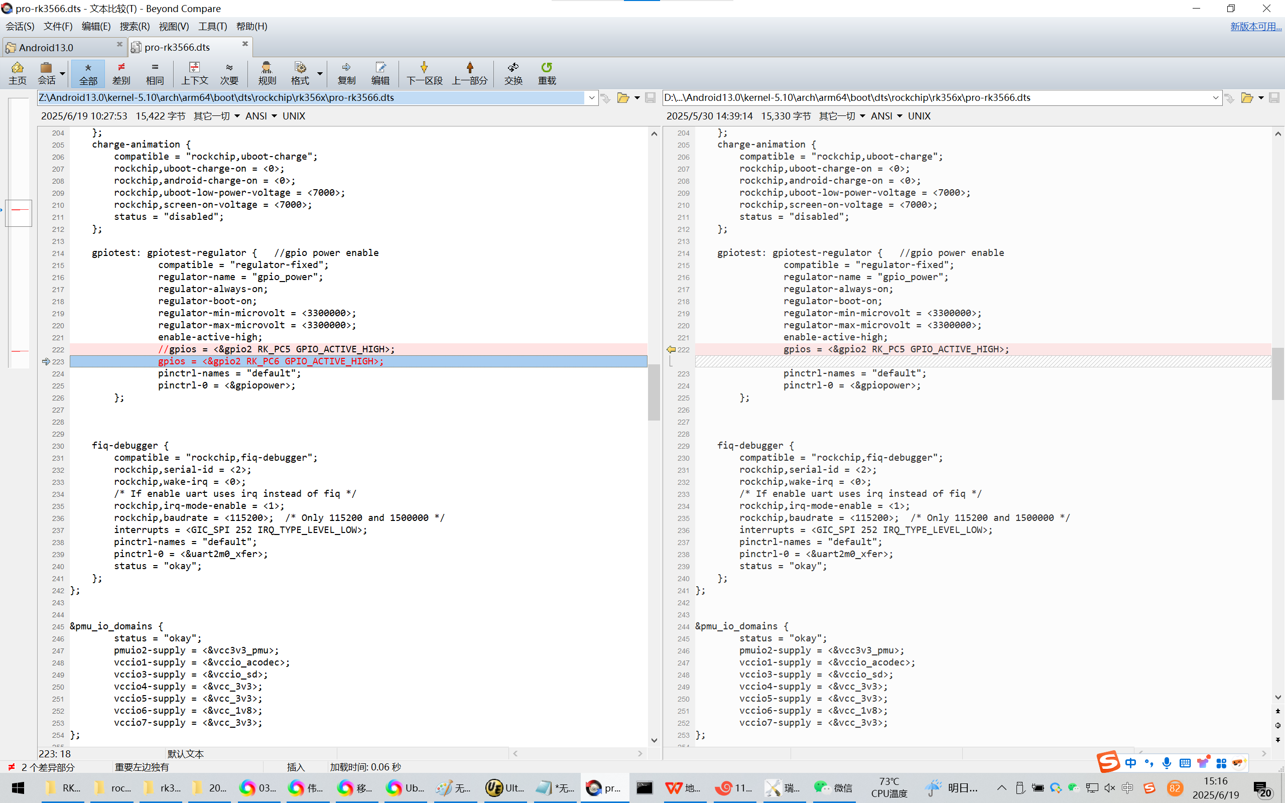
20250619在荣品的PRO-RK3566开发板的Android13系统的uboot阶段就拉高GPIO2C6
gpiotest: gpiotest-regulator { //gpio power enable
compatible = "regulator-fixed";
regulator-name = "gpio_power";
regulator-always-on;
regulator-boot-on;
regulator-min-microvolt = <3300000>;
regulator-max-microvolt = <3300000>;
enable-active-high;
//gpios = <&gpio2 RK_PC5 GPIO_ACTIVE_HIGH>;
gpios = <&gpio2 RK_PC6 GPIO_ACTIVE_HIGH>;
pinctrl-names = "default";
pinctrl-0 = <&gpiopower>;
};
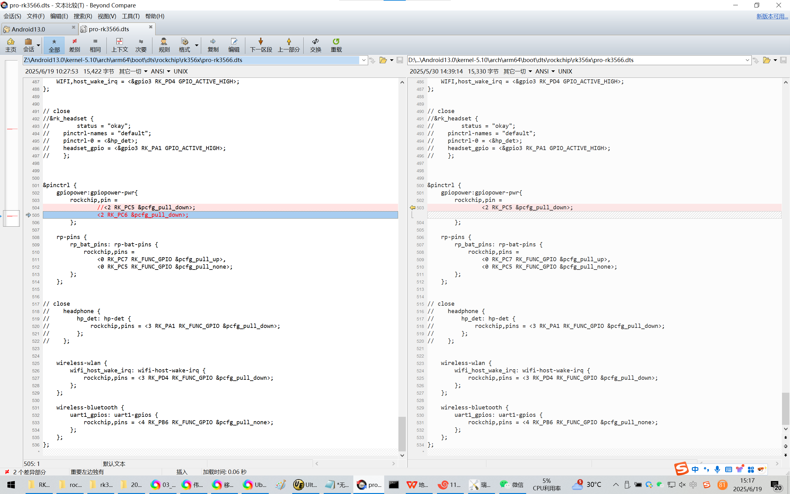
gpiopower:gpiopower-pwr{
rockchip,pin =
//<2 RK_PC5 &pcfg_pull_down>;
<2 RK_PC6 &pcfg_pull_down>;
};
20250619在荣品的PRO-RK3566开发板的Android13系统的uboot阶段就拉高GPIO2C6
2025/6/19 15:10
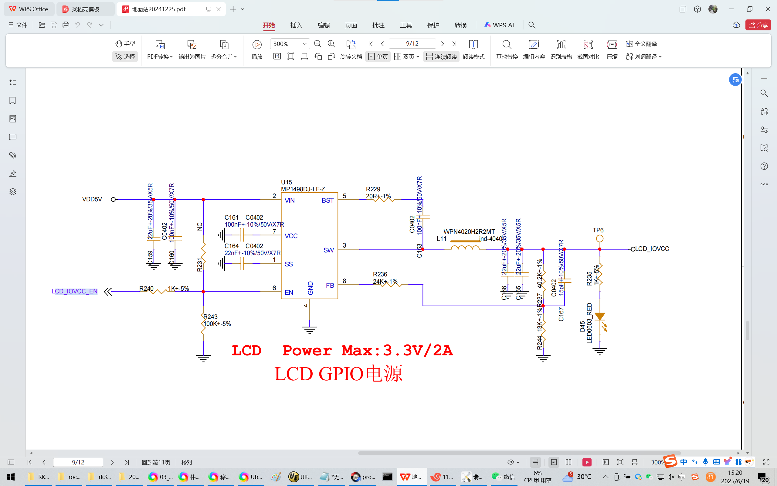
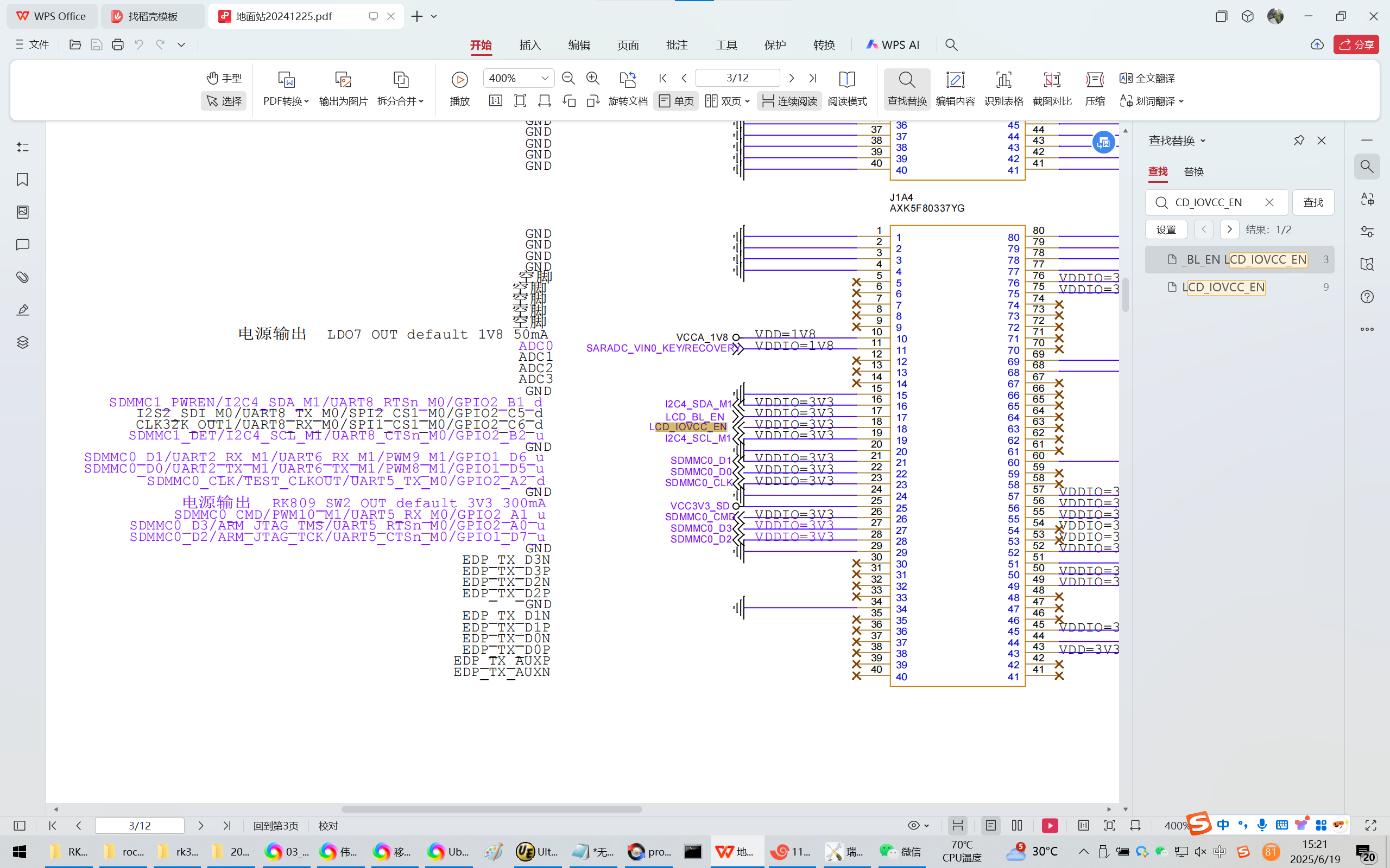
缘起:荣品的PRO-RK3566项目的GPIO2C6引脚控制着LCD屏的VDDI引脚。
因此需要在上电开机的时候,马上就拉高GPIO2C6【uboot阶段】。
实践证明/【用示波器】确认:
在uboot阶段拉高GPIO控制LCD屏的电源GPIO2C6,发现是在现阶段大概是在上电大概1.4s-1.5s的时候,VDDI和AVDD同时拉高。
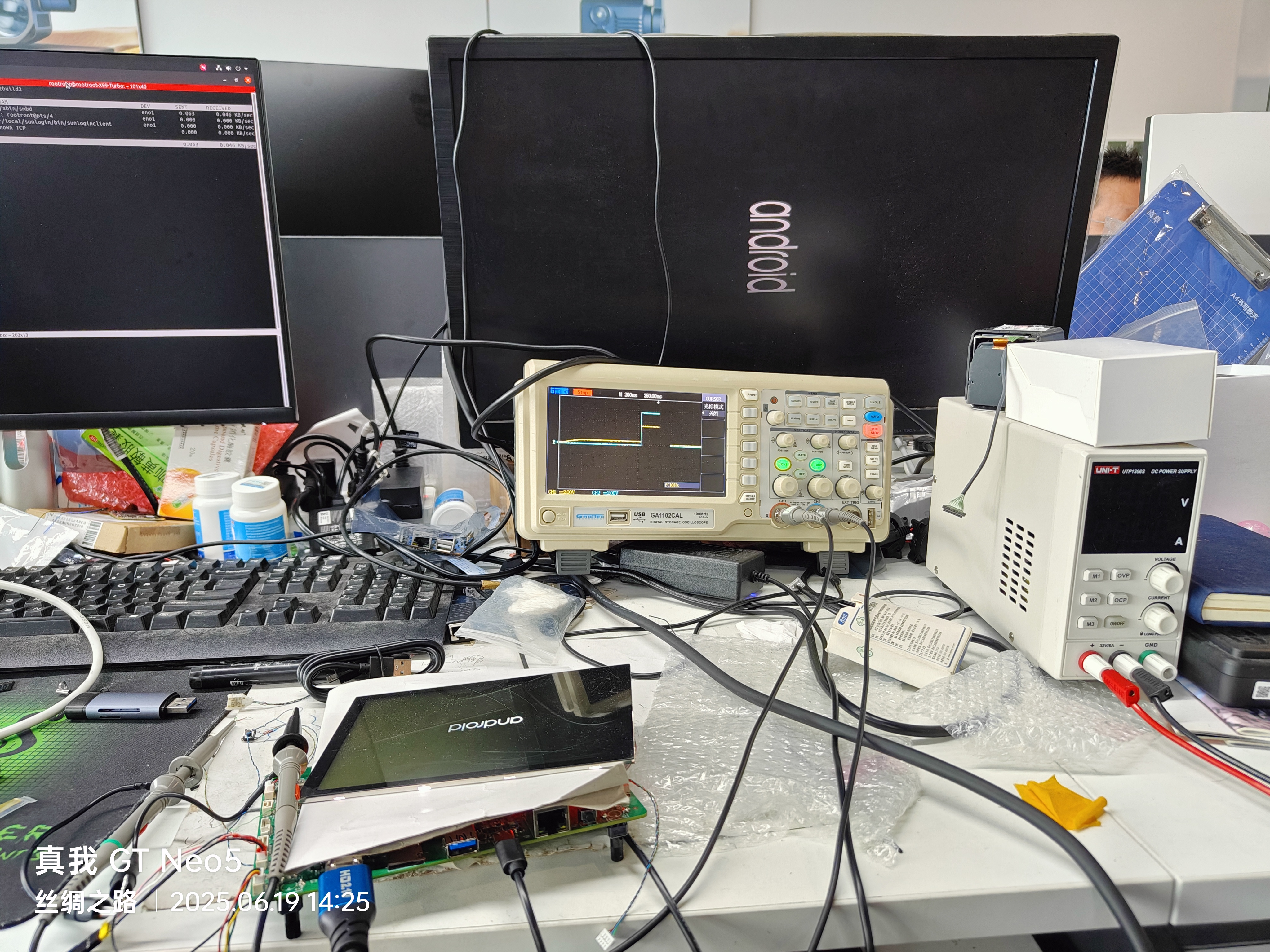
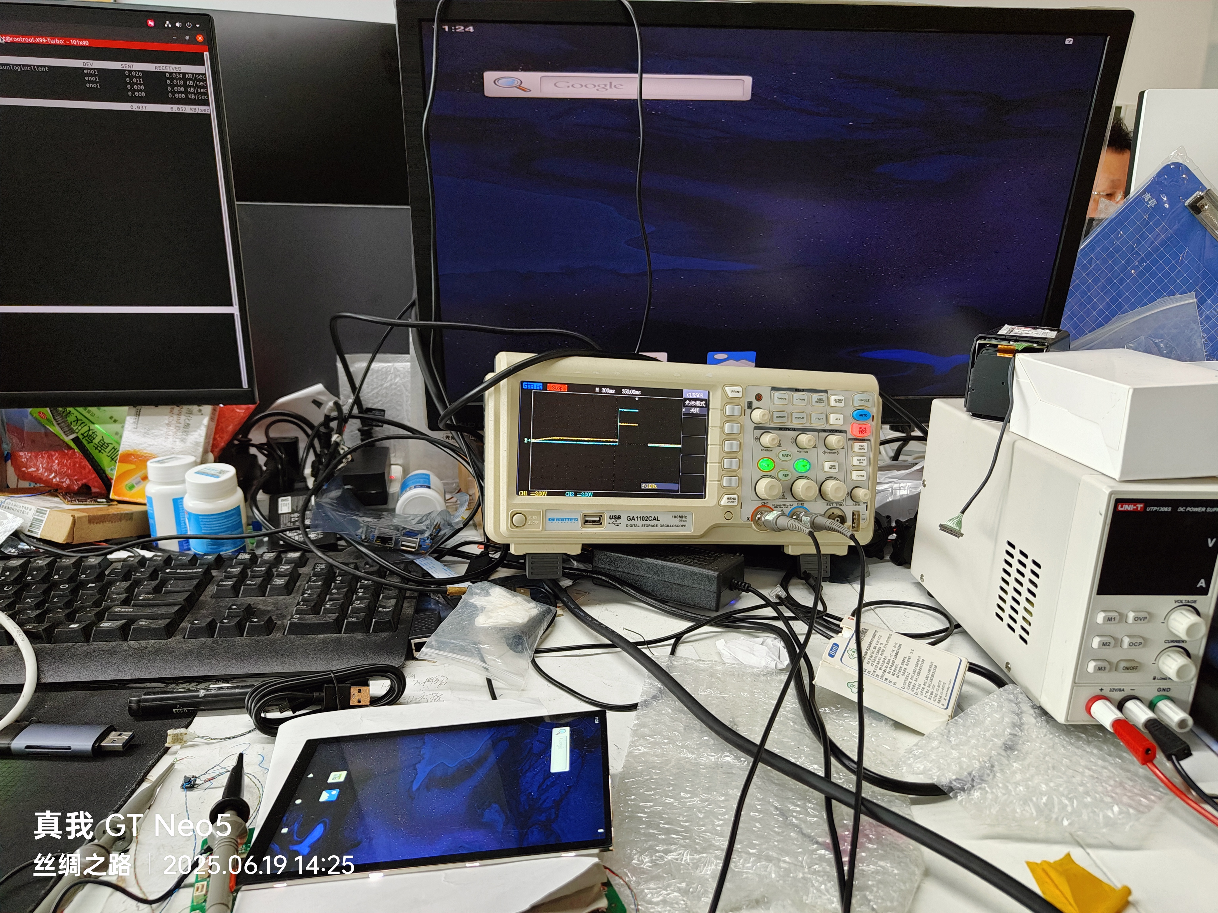
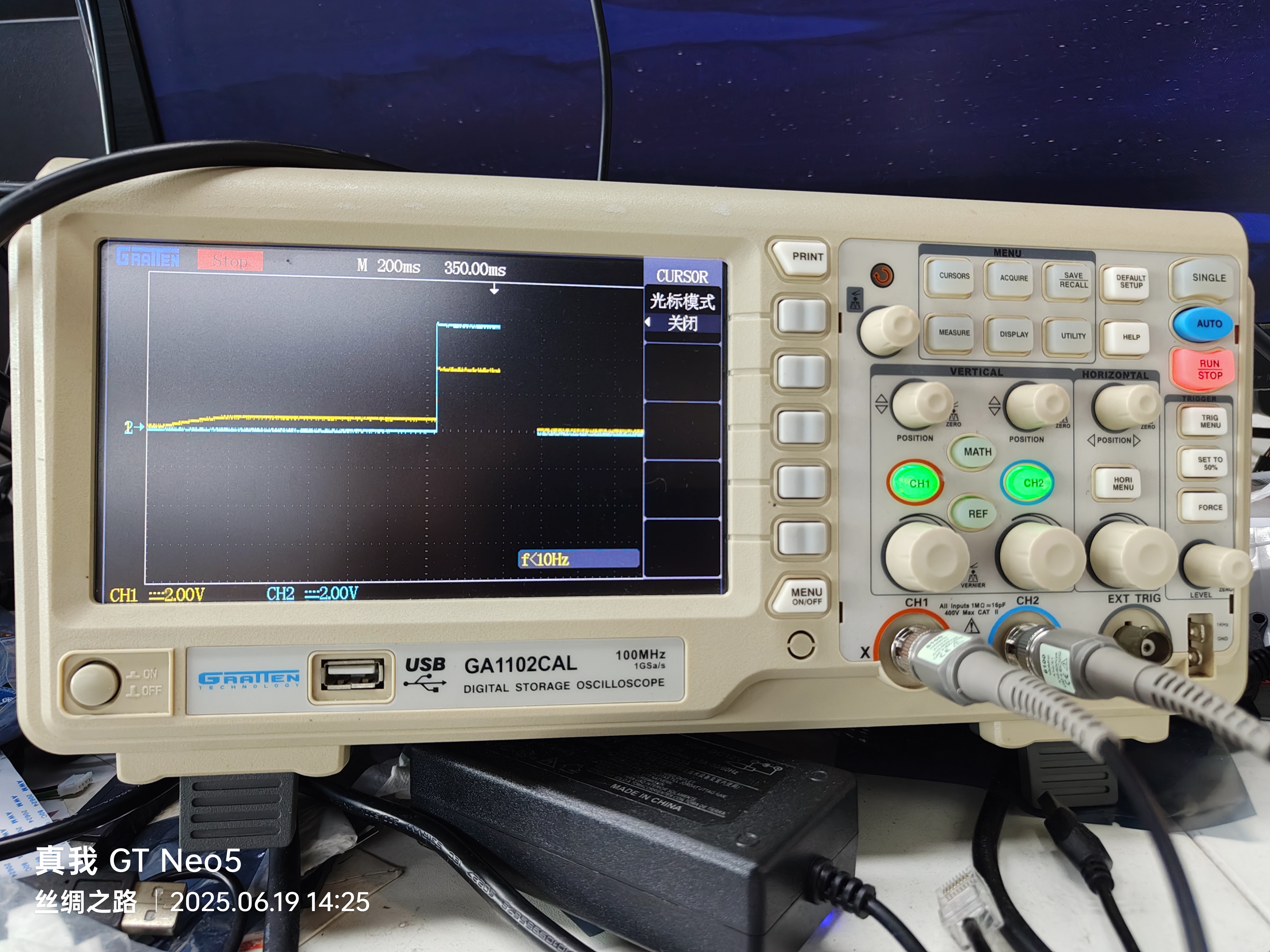
LCD_IOVCC_EN
Z:\Android13.0\kernel-5.10\arch\arm64\boot\dts\rockchip\rk356x\pro-rk3566.dts
// SPDX-License-Identifier: (GPL-2.0+ OR MIT)
/*
* Copyright (c) 2020 Rockchip Electronics Co., Ltd.
*
*/
/dts-v1/;
//rk3566-evb1-ddr4-v10
//#include "rk3566-evb1-ddr4-v10.dtsi"
#include "rk3566-evb-rpdzkj-rk809-tcs4525.dtsi"
#include "../rk3568-android.dtsi"
/*************************camera***********************/
#include "rp-mipi-camera-gc2093-rk3566.dtsi"
/***************************************************/
/*************************adc key***********************/
#include "rp-adc-key.dtsi"
/***************************************************/
/*************************gmac***********************/
#include "rp-gmac1-m0-pro-rk3566.dtsi"
/***************************************************/
/*************************SATA***********************/
//#include "rk3568-sata1.dtsi"
#include "rk3568-sata2.dtsi"
/***************************************************/
/****************** SINGLE LCD ***************/
#include "pro-rk3566-single-lcd-gpio.dtsi"
/* HDMI */
#include "rp-lcd-hdmi.dtsi"
/* MIPI0 */
//#include "rp-lcd-mipi0-5-720-1280-v2-boxTP.dtsi"
//#include "rp-lcd-mipi0-5.5-720-1280.dtsi"
//#include "rp-lcd-mipi0-5.5-720-1280-v2.dtsi"
//#include "rp-lcd-mipi0-5.5-1080-1920.dtsi"
//#include "rp-lcd-mipi0-7-1024-600.dtsi"
//#include "rp-lcd-mipi0-7-720-1280.dtsi"
#include "rp-lcd-mipi0-7-1200-1920.dtsi"
//#include "rp-lcd-mipi0-8-800-1280.dtsi"
//#include "rp-lcd-mipi0-8-800-1280-v2.dtsi"
//#include "rp-lcd-mipi0-8-800-1280-v3.dtsi"
//#include "rp-lcd-mipi0-8-1200-1920.dtsi"
//#include "rp-lcd-mipi0-10-800-1280.dtsi"
//#include "rp-lcd-mipi0-10-800-1280-v2.dtsi"
//#include "rp-lcd-mipi0-10-800-1280-v3.dtsi"
//#include "rp-lcd-mipi0-10-1920-1200.dtsi"
//#include "rp-lcd-mipi0-10-1920-1200-jc.dtsi"
/* MIPI1 */
//#include "rp-lcd-mipi1-7-1024-600.dtsi"
/* LVDS */
//#include "rp-lcd-lvds-10-1024-600.dtsi"
//#include "rp-lcd-lvds-7-1024-600-v2.dtsi"
//#include "rp-lcd-lvds-10-1280-800.dtsi"
/* EDP */
//#include "rp-lcd-edp-13-1920-1080.dtsi"
/ {
model = "pro-rk3566";
compatible = "rpdzkj,pro-rk3566", "rockchip,rk3566";
rp_power{
status = "okay";
compatible = "rp_power";
rp_not_deep_sleep = <1>;
//#define GPIO_FUNCTION_OUTPUT 0
//#define GPIO_FUNCTION_INPUT 1
//#define GPIO_FUNCTION_IRQ 2
//#define GPIO_FUNCTION_FLASH 3
//#define GPIO_FUNCTION_OUTPUT_CTRL 4
pwr_5v_3v3 { //3.3v 5v enable
gpio_num = <&gpio2 RK_PB3 GPIO_ACTIVE_HIGH>;
gpio_function = <0>;
};
led { //system led
gpio_num = <&gpio3 RK_PC2 GPIO_ACTIVE_HIGH>;
gpio_function = <3>;
};
usb_pwr { //usb host power and otg power
gpio_num = <&gpio0 RK_PA6 GPIO_ACTIVE_HIGH>;
gpio_function = <4>;
};
usb_rst { //usb hub reset
gpio_num = <&gpio0 RK_PB0 GPIO_ACTIVE_HIGH>;
gpio_function = <4>;
};
spk_en { //SPK ENABLE
gpio_num = <&gpio4 RK_PC4 GPIO_ACTIVE_HIGH>;
gpio_function = <4>;
};
spk_mute { //SPK MUTE
gpio_num = <&gpio0 RK_PA0 GPIO_ACTIVE_LOW>;
gpio_function = <4>;
};
usb_mode { //OTG SWITCH
gpio_num = <&gpio0 RK_PC2 GPIO_ACTIVE_LOW>;
gpio_function = <0>;
};
Equipment_EN { // Equipment_EN rongping PRO-RK3566 POWER
gpio_num = <&gpio3 RK_PA1 GPIO_ACTIVE_HIGH>;
gpio_function = <0>;
};
//LCD_BL_EN { // LCD_BL_EN rongping PRO-RK3566 POWER
// gpio_num = <&gpio2 RK_PC5 GPIO_ACTIVE_LOW>;
// gpio_function = <0>;
//};
//LCD_BL_EN { // LCD_BL_EN rongping PRO-RK3566 POWER
// gpio_num = <&gpio2 RK_PC5 GPIO_ACTIVE_HIGH>;
// gpio_function = <0>;
//};
};
rp_gpio{
status = "okay";
compatible = "rp_gpio";
/***** SPI_FLASH ********/
gpio1d0 {
gpio_num = <&gpio1 RK_PD0 GPIO_ACTIVE_HIGH>;
gpio_function = <0>;
};
gpio1d1 {
gpio_num = <&gpio1 RK_PD1 GPIO_ACTIVE_HIGH>;
gpio_function = <0>;
};
gpio1d2 {
gpio_num = <&gpio1 RK_PD2 GPIO_ACTIVE_HIGH>;
gpio_function = <0>;
};
gpio1d3 {
gpio_num = <&gpio1 RK_PD3 GPIO_ACTIVE_HIGH>;
gpio_function = <0>;
};
gpio1d4 {
gpio_num = <&gpio1 RK_PD4 GPIO_ACTIVE_HIGH>;
gpio_function = <0>;
};
/***** PDM ********/
gpio4a0 {
gpio_num = <&gpio4 RK_PA0 GPIO_ACTIVE_HIGH>;
gpio_function = <0>;
};
gpio4a1 {
gpio_num = <&gpio4 RK_PA1 GPIO_ACTIVE_HIGH>;
gpio_function = <0>;
};
gpio4a2 {
gpio_num = <&gpio4 RK_PA2 GPIO_ACTIVE_HIGH>;
gpio_function = <0>;
};
gpio4a3 {
gpio_num = <&gpio4 RK_PA3 GPIO_ACTIVE_HIGH>;
gpio_function = <0>;
};
gpio1a4 {
gpio_num = <&gpio1 RK_PA4 GPIO_ACTIVE_HIGH>;
gpio_function = <0>;
};
gpio3c1 {
gpio_num = <&gpio3 RK_PC1 GPIO_ACTIVE_HIGH>;
gpio_function = <0>;
};
};
test-power {
/** disable for use rk809-battery */
status = "disabled";
};
charge-animation {
compatible = "rockchip,uboot-charge";
rockchip,uboot-charge-on = <0>;
rockchip,android-charge-on = <0>;
rockchip,uboot-low-power-voltage = <7000>;
rockchip,screen-on-voltage = <7000>;
status = "disabled";
};
gpiotest: gpiotest-regulator { //gpio power enable
compatible = "regulator-fixed";
regulator-name = "gpio_power";
regulator-always-on;
regulator-boot-on;
regulator-min-microvolt = <3300000>;
regulator-max-microvolt = <3300000>;
enable-active-high;
//gpios = <&gpio2 RK_PC5 GPIO_ACTIVE_HIGH>;
gpios = <&gpio2 RK_PC6 GPIO_ACTIVE_HIGH>;
pinctrl-names = "default";
pinctrl-0 = <&gpiopower>;
};
fiq-debugger {
compatible = "rockchip,fiq-debugger";
rockchip,serial-id = <2>;
rockchip,wake-irq = <0>;
/* If enable uart uses irq instead of fiq */
rockchip,irq-mode-enable = <1>;
rockchip,baudrate = <115200>; /* Only 115200 and 1500000 */
interrupts = <GIC_SPI 252 IRQ_TYPE_LEVEL_LOW>;
pinctrl-names = "default";
pinctrl-0 = <&uart2m0_xfer>;
status = "okay";
};
};
&pmu_io_domains {
status = "okay";
pmuio2-supply = <&vcc3v3_pmu>;
vccio1-supply = <&vccio_acodec>;
vccio3-supply = <&vccio_sd>;
vccio4-supply = <&vcc_3v3>;
vccio5-supply = <&vcc_3v3>;
vccio6-supply = <&vcc_1v8>;
vccio7-supply = <&vcc_3v3>;
};
&cpu0_opp_table {
opp-408000000 {
opp-hz = /bits/ 64 <408000000>;
opp-microvolt = <825000 825000 1150000>;
opp-microvolt-L0 = <825000 825000 1150000>;
opp-microvolt-L1 = <800000 800000 1150000>;
opp-microvolt-L2 = <800000 800000 1150000>;
clock-latency-ns = <40000>;
};
opp-600000000 {
opp-hz = /bits/ 64 <600000000>;
opp-microvolt = <850000 850000 1150000>;
opp-microvolt-L0 = <850000 850000 1150000>;
opp-microvolt-L1 = <825000 825000 1150000>;
opp-microvolt-L2 = <825000 825000 1150000>;
clock-latency-ns = <40000>;
};
opp-816000000 {
opp-hz = /bits/ 64 <816000000>;
opp-microvolt = <900000 900000 1150000>;
opp-microvolt-L0 = <900000 900000 1150000>;
opp-microvolt-L1 = <875000 875000 1150000>;
opp-microvolt-L2 = <875000 875000 1150000>;
clock-latency-ns = <40000>;
opp-suspend;
};
opp-1104000000 {
opp-hz = /bits/ 64 <1104000000>;
opp-microvolt = <950000 950000 1150000>;
opp-microvolt-L0 = <950000 950000 1150000>;
opp-microvolt-L1 = <925000 925000 1150000>;
opp-microvolt-L2 = <925000 925000 1150000>;
clock-latency-ns = <40000>;
};
opp-1416000000 {
opp-hz = /bits/ 64 <1416000000>;
opp-microvolt = <1000000 1000000 1150000>;
opp-microvolt-L0 = <1000000 1000000 1150000>;
opp-microvolt-L1 = <975000 975000 1150000>;
opp-microvolt-L2 = <975000 975000 1150000>;
clock-latency-ns = <40000>;
};
opp-1608000000 {
opp-hz = /bits/ 64 <1608000000>;
opp-microvolt = <1050000 1050000 1150000>;
opp-microvolt-L0 = <1050000 1050000 1150000>;
opp-microvolt-L1 = <1025000 1025000 1150000>;
opp-microvolt-L2 = <1025000 1025000 1150000>;
clock-latency-ns = <40000>;
};
opp-1800000000 {
opp-hz = /bits/ 64 <1800000000>;
opp-microvolt = <1100000 1100000 1150000>;
opp-microvolt-L0 = <1100000 1100000 1150000>;
opp-microvolt-L1 = <1075000 1075000 1150000>;
opp-microvolt-L2 = <1075000 1075000 1150000>;
clock-latency-ns = <40000>;
};
};
&i2c1 {
status = "okay";
};
&i2c4 {
status = "okay";
pinctrl-names = "default";
pinctrl-0 = <&i2c4m1_xfer>;
rtc@51 {
status = "okay";
compatible = "rtc,hym8563";
reg = <0x51>;
};
};
&uart3 {
status = "okay";
pinctrl-names = "default";
pinctrl-0 = <&uart3m0_xfer>;
};
&uart6 {
status = "okay";
pinctrl-names = "default";
pinctrl-0 = <&uart6m0_xfer>;
};
&uart7 {
status = "okay";
pinctrl-names = "default";
pinctrl-0 = <&uart7m0_xfer>;
};
&uart9 {
status = "okay";
pinctrl-names = "default";
pinctrl-0 = <&uart9m0_xfer>;
};
&spi1 {
status = "okay";
spi1_dev@0 {
compatible = "rockchip,spidev";
reg = <0>;
spi-max-frequency = <12000000>;
spi-lsb-first;
};
};
&spi2 {
status = "okay";
spi2_dev@0 {
compatible = "rockchip,spidev";
reg = <0>;
spi-max-frequency = <12000000>;
spi-lsb-first;
};
};
&spi3 {
status = "okay";
num-cs = <1>;
pinctrl-0 = <&spi3m1_cs0 &spi3m1_pins>;
pinctrl-1 = <&spi3m1_cs0 &spi3m1_pins_hs>;
spi3_dev@0 {
compatible = "rockchip,spidev";
reg = <0>;
spi-max-frequency = <12000000>;
spi-lsb-first;
};
};
&edp {
/** delete hdp gpio that pro3566 donot use */
/delete-property/ hpd-gpios;
};
&dmc {
status = "disabled";
};
&dfi {
status = "disabled";
};
&rk809 {
battery {
compatible = "rk817,battery";
pinctrl-names = "default";
pinctrl-0 = <&rp_bat_pins>;
ocv_table = < 7024 7072 7080 7096 7104 7112 7120
7136 7152 7168 7184 7224 7264 7320
7392 7512 7612 7724 7828 7928 8100>;
design_capacity = <5000>;
design_qmax = <5100>;
bat_res = <100>;
sleep_enter_current = <300>;
sleep_exit_current = <300>;
sleep_filter_current = <100>;
power_off_thresd = <7024>;
zero_algorithm_vol = <7400>;
max_soc_offset = <60>;
monitor_sec = <5>;
sample_res = <20>;
bat_res_up = <140>;
bat_res_down = <20>;
virtual_power = <0>; //test mode, 1 to force report 66%
energy_mode = <0>;
register_chg_psy = <1>; //rk817 report charge state
plug-det-gpio = <&gpio0 RK_PC7 GPIO_ACTIVE_LOW>; //rpdzkj add for detect charge state, need register_chg_psy = 1, active state is plugin.
full-det-gpio = <&gpio0 RK_PC5 GPIO_ACTIVE_HIGH>; //rpdzkj add for detect charge status whether is full.
status = "disabled";
};
};
&sdmmc2 {
max-frequency = <150000000>;
supports-sdio;
bus-width = <4>;
disable-wp;
cap-sd-highspeed;
cap-sdio-irq;
keep-power-in-suspend;
mmc-pwrseq = <&sdio_pwrseq>;
non-removable;
pinctrl-names = "default";
pinctrl-0 = <&sdmmc2m0_bus4 &sdmmc2m0_cmd &sdmmc2m0_clk>;
sd-uhs-sdr104;
status = "okay";
};
&uart1 {
status = "okay";
pinctrl-names = "default";
pinctrl-0 = <&uart1m1_xfer &uart1m1_ctsn>;
};
&wireless_bluetooth {
uart_rts_gpios = <&gpio4 RK_PB6 GPIO_ACTIVE_LOW>;
pinctrl-names = "default", "rts_gpio";
pinctrl-0 = <&uart1m1_rtsn>;
pinctrl-1 = <&uart1_gpios>;
BT,reset_gpio = <&gpio4 RK_PA5 GPIO_ACTIVE_HIGH>;
BT,wake_gpio = <&gpio4 RK_PA6 GPIO_ACTIVE_HIGH>;
BT,wake_host_irq = <&gpio4 RK_PB1 GPIO_ACTIVE_HIGH>;
status = "okay";
};
&wireless_wlan {
pinctrl-names = "default";
pinctrl-0 = <&wifi_host_wake_irq>;
WIFI,host_wake_irq = <&gpio3 RK_PD4 GPIO_ACTIVE_HIGH>;
};
// close
//&rk_headset {
// status = "okay";
// pinctrl-names = "default";
// pinctrl-0 = <&hp_det>;
// headset_gpio = <&gpio3 RK_PA1 GPIO_ACTIVE_HIGH>;
// };
&pinctrl {
gpiopower:gpiopower-pwr{
rockchip,pin =
//<2 RK_PC5 &pcfg_pull_down>;
<2 RK_PC6 &pcfg_pull_down>;
};
rp-pins {
rp_bat_pins: rp-bat-pins {
rockchip,pins =
<0 RK_PC7 RK_FUNC_GPIO &pcfg_pull_up>,
<0 RK_PC5 RK_FUNC_GPIO &pcfg_pull_none>;
};
};
// close
// headphone {
// hp_det: hp-det {
// rockchip,pins = <3 RK_PA1 RK_FUNC_GPIO &pcfg_pull_down>;
// };
// };
wireless-wlan {
wifi_host_wake_irq: wifi-host-wake-irq {
rockchip,pins = <3 RK_PD4 RK_FUNC_GPIO &pcfg_pull_down>;
};
};
wireless-bluetooth {
uart1_gpios: uart1-gpios {
rockchip,pins = <4 RK_PB6 RK_FUNC_GPIO &pcfg_pull_none>;
};
};
};
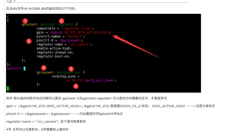
在主dts文件rd-rk3588.dts的最后添加以下代码,
{
gpiotest: gpiotest-regulator { //gpio power enable
compatible = "regulator-fixed";
gpios = <&gpio4 RK_PC6 GPIO_ACTIVE_HIGH>;
pinctrl-names = "default";
pinctrl-0 = <&gpiopower>;
regulator-name = "vcc_camear";
enable-active-high;
regulator-always-on;
regulator-boot-on;
};
}
&pinctrl {
gpiopower:gpiopower-pwr{
rockchip,pin =
<4 RK_PC6 &pcfg_pull_down>;
};
};
其中 箭头指向和数字标点的都可以更改 gpiotest 以及gpiotest-regulator 可以更改为你需要的名字,不重复即可
gpios = <&gpio4 RK_PC6 GPIO_ACTIVE_HIGH>;&gpio4 RK_PC6 是根据GPI04_C6_d 修改; GPIO_ACTIVE_HIGH --->设置为高电平
pinctrl-0 = <&gpiopower>;&gpiopower----->为此截图中的&pinctrl4号标点
regulator-name = "vcc_camear";这个值可随意更改
4号 五号可以任意取名,6号需要和上面同步

openvela 操作系统专为 AIoT 领域量身定制,以轻量化、标准兼容、安全性和高度可扩展性为核心特点。openvela 以其卓越的技术优势,已成为众多物联网设备和 AI 硬件的技术首选,涵盖了智能手表、运动手环、智能音箱、耳机、智能家居设备以及机器人等多个领域。
更多推荐
 7
7 0
0- 0


 已为社区贡献6条内容

所有评论(0)